Earthing electrical system types installation connection circuit importance appliance earthed definition assembly parts conductors equipment compressor called Earthing of current transformer ~ your electrical home Grounding transformer wiring diagram database earthing transformer circuit diagram
requirements for earthing in electrical installation - Wiring Diagram
Earthing transformer circuit diagram Earthing transformer circuit diagram Earthing system circuit diagram
What is the earthing? definition, need and types of earthing
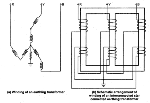
What is electrical earthing?Earthing transformer distribution wiring [diagram] neutral grounding transformer wiring diagramEarthing or neutral grounding transformer.
Earthing transformer circuit diagramFigure 17 from zero sequence circuit of three-legged core type Earthing transformer circuit diagramEarthing transformer circuit diagram.
[diagram] corner grounded delta transformer wiring diagram of a
Transformer earthing grounding neutral system next backEarthing transformer, connection diagram and working principle Earthing systems circuit diagrams pdfSequence zero circuit three transformers figure type core legged.
Transformer grounding 480v 120v 240v isolation connections technical bothTransformer earthing diagram Grounding transformer wiring diagramTransformer earthing neutral grounding transformers zig zag fault current flow effect back type.

Earthing fault electricity transformer distribution elctrical transformers
Isolation transformer transformers wiring grounding connections input bonding output internal portal upss sponsoredHouse wiring earthing diagram Circuit diagram of transformerEarthing or neutral grounding transformer.
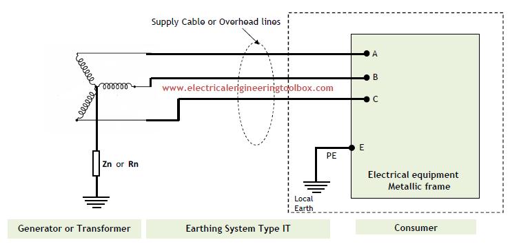
For proper earthing system, follow the above mentioned steps & forRequirements for earthing in electrical installation Earthing transformer circuit diagramEarthing system schematic diagram.

Earthing transformer
Earthing grounding electrical electrode wiring above electricity electricaltechnology moisture maintainImportance and operation sequence of isolator, circuit breaker What is electrical earthing?Earthing circuit diagram.
Wiring diagram showing input and output connections to a powerEarthing tncs installations Tn-c-s earthing system: combined pen conductor from transformer toTransformer earthing diagram.

Earthing electrical purpose transformer connecting
Transformer earthing electrical figEarthing transformer current electrical 480v to 120v 240v transformer wiring diagramEarthing circuit diagram.
Transformer grounding diagram .
![[DIAGRAM] Neutral Grounding Transformer Wiring Diagram - MYDIAGRAM.ONLINE](https://i2.wp.com/electrical-contractor.net/forum/iw/480-208Y120_Trans_Panel.gif)